Translate The Website (Starts on Home Page)    
RA Mayes EMC Test
Follow Us On LinkedIn   Twitter   facebook
R A Mayes Logo and Home Page Call Nationwide 1-800-742-9447


GPS Antennas
Buy American Act Compliant 
New PRC-COM Logo

Made In the USA 


PRC-COM GPS Helical Antennas

Custom Lower Frequency Helical Antennas Available

PRC-COM HX-1400 Helical Antenna Covers Entire GPS L1, L2, L3, L4 & L5 Frequency Bands

Available in RHCP (Standard) and LHCP (No Added Cost Option)

PRC COM GPS Helix Antenna

Model pdf

Frequency (MHz)

Gain (dB)

Beam Width

(degrees)

Max Power

(watts)

HX-0700-06-R

540 - 855

8.2

45

Type-N:200

HX-0800-06-R

625 - 975

8.4

44

Type-N:200

HX-0900-06-R

700 - 1100

8.5

44

Type-N:200

HX-0900-08-R

700 - 1100

8.7

38

Type-N:200

HX-0900-10-R

700 - 1100

11.5

34

Type-N:200

HX-0900-13-R

700 - 1100

13.2

30

Type-N:200

HX-1000-06-R

780 - 1220

8.2

45

Type-N:200

HX-1000-08-R

780 - 1220

9.5

39

Type-N:200

HX-1000-10-R

780 - 1220

11

35

Type-N:200

HX-1200-06-R

940 - 1470

8.5

44

Type-N:200

HX-1200-08-R

940 - 1470

9.7

38

Type-N:200

HX-1200-10-R

 1000 - 1500

11

35

Type-N:200

HX-1200-12-R

1000 - 1500

12

32

Type-N:200

HX-1200-13-R

1000 - 1500

14.2

31

Type-N:200

HX-1200-14-R

1000 - 1500

15.2

30

Type-N:200

HX-1400-06-R

1100 - 1700

8.2

45

Type-N:200

HX-1400-08-R

1100 - 1700

9.5

39

Type-N:200

HX-1400-10-R

1100 - 1700

10.4

35

Type-N:200

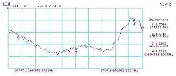
HX-1400-10-R VSWR Plot (pdf)   (jpg)


HX-1400-13-R 

1100 - 1700

11.6

31

Type-N:200

HX-2000-10-R

1500 - 2440

10.4

35

Type-N:200

HX-2500-10-R

1950 - 3000

11.5

32.9

Type-N:200

HX-3500-10-R

2900 - 4200

11

32.9

Type-N:200

HX-4500-10-R

3800 - 5200

10.2

37

SMA:50

HX-5500-10-R

4800 - 6000

10.2

36

SMA:50


Catalog

TMC Logo

...reasonable and timely solutions for the most  difficult engineering requirements

Manufactured and Serviced in Las Cruces, NM

TMC Design FS-1050 RHCP GPS Antenna

FS-1050

1.2 to 1.6 GHz

TMC Design FS-1050 Antenna

GPS Antenna

Data

High Power GPS Antenna

Data

The FS-1050 (-HP) is a wide band, flat spiral transmit and receive antenna contained within a rugged, sealed epoxy-glass radome.


The result is an exact threat representative antenna in a robust package with standard type-N connectors.


The antenna is available in a high power version and with a deployable tower mount.


The unit is also available with internal modulator and amplifier to operate as a stand alone jammer system.


Threat Representative

Linear Polarization

Rugged Construction

Electrical Specifications

Model:

FS-1050

Frequency:

1.2 - 1.6 GHz

Gain:

7 dBiC

Power Handling:

25 watts (CW) 100 watts (CW) -HP

Polarization:

RHCP

VSWR:

1.5:1 typical   2.0:1 maximum

Beamwidth:

65 x 65 degrees (center frequency)

Mechanical Specifications

Dimensions:

11" x 11" x 3" (27.9cm x 27.9cm x 7.6cm)

Weight:

5.25 lbs. (2.38 kg)

Temperature:

-20° to +150° F (-28.8° to 65.5° C)

Environmental:

Harsh

Connector:

Type-N (other types available)


TMC Design FS-1050 Antenna


 Chart


Graph


TMC Design BC-0300 Disk Spiral GPS Antenna

BC-0300

0.5 to 3 GHz

GPS Antenna


TMC Design BC-0300 Antenna


TMC Design BC-0300 Antenna


Data 


The BC-0300 antenna is a wide-band, electrically small biconical monopole antenna designed for low frequency testing and wideband communications systems, eliminating the need for large antennas or tuning systems.


The antenna is housed and sealed in a rugged radome to ensure long life and electrical repeatability.


Threat Representative

Linear Polarization

Rugged Construction

Electrical Specifications

Model:

BC-0300

Frequency:

500 MHz - 3 GHz

Gain:

3.5 dB

Power Handling:

100 watts (CW), high power version available

Polarization:

Linear (typically vertical)

VSWR:

3:1 typical

Beamwidth:

360 x 85 degrees (center frequency)

Mechanical Specifications

Dimensions:

8.5" High x 5.0" Diameter

Weight:

4 lbs.

Temperature:

-20° to +150° F (-28.8° to 65.5° C)

Environmental:

Harsh

Connector:

Type-N (other types available)


BC-0300 Pattern EL 1000MHz


TMC Design HE-238 Helical GPS Antenna

HE-238-8

HE-238-10

HE-238-13


1.2 to 1.8 GHz


GPS Antenna


TMC Design HE-238 Helical Antenna


Data 


The HE-238 is a high power, wide band severe duty antenna for both military and commercial applications. The antenna is constructed entirely of aircraft certified 6061-T6 aluminum and G-10 fiberglass with copper radiator in a 100% sealed radome.


They are available as a single helix or as a dual mounted pair of tower mounted antennas (shown left).


Several options are available for the tower mounted antennas including motorized azimuth rotators and adjustable elevation mounts.


These antennas will provide years of trouble free service in the most sever environments and are currently in use by several U.S. Military installations in remote locations.


High Power

Single or Dual Helix

Rugged Construction

Electrical Specifications

Model:

HE-238

Frequency:

1.2 - 1.8 GHz

Gain:

HE-238-8    10.5dB

HE-238-10  11.5 dB

HE-238-13  13 dB

Power Handling:

500 Watts

Polarization:

RHCP

VSWR:

2:1 maximum (See Graph)

Beamwidth:

HE-238-8 40°   HE-238-10 35°   HE-238-13 30°

Mechanical Specifications

Dimensions:


Weight:

(dual mount) 21 lbs.

Temperature:

-20° to +150° F (-28.8° to 65.5° C)

Environmental:

Harsh

Connector:

Type-N (other types available)

Azimuth Movement:

360 x 90 degrees (center frequency) 360 deg, w rotator

Elevation Movement:

-15 to 15 deg, manual


Pattern


Graph

TMC Design Helicone Antenna (1.2 - 1.6 GHz)

HC-238-13


 Helicone Antenna


1.2 GHz - 1.6 GHz


L-Band Frequency


RHCP  Polarization


TMC Design Helicone Antenna


Data 

The HC-238-13 antenna is a high-power L-Band Helicone antenna that uses a helix-conical horn combination. This combination provides low side lobe levels while keeping a solid gain.
 

  • L-Band Frequency

  • RHCP

  • Low side lobe level

  • High Power

  • Rugged design

  • Anechoic Chamber Tested


Electrical Specifications

Model:

HC-238-13

Frequency:

1.2 - 1.6 GHz

Gain (dB):

14.7 @ L2, 13.1 @ L1

Power Handling:

500 watts CW

Polarization:

Circular (RHCP)

VSWR:

2.0:1 maximum

HPBW:

33.5° @ L2, 30° @ L1

Sidelobe:

-31 dB @ L1, -28 dB @ L2

Mechanical Specifications

Model:

HC-238-13

Dimensions:

24.5" diameter x 23.5" length

Weight:

17.5 lbs


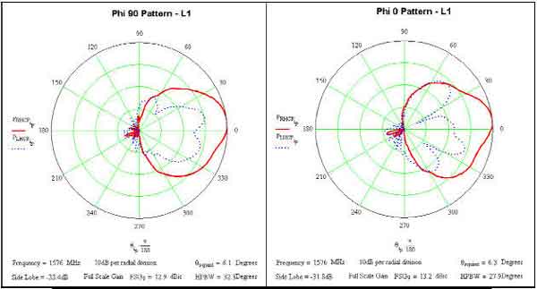
Pattern

TMC Design GPS Direction Finding Antenna

HE-238-165-HH


1.2 to 1.6 GHz


GPS Directional Antenna


TMC Design GPS Directional Antenna


TMC Design GPS Direction Finder Antenna


Data 


The HE-238-165-HH is a hand held directional antenna. The antenna is constructed entirely of aircraft certified 6061-T6 aluminum and G-10 fiberglass with copper radiator in a 100% sealed radome.


This antenna was custom matched from 1.2 to 1.6 GHz to have the lowest VSWR possible, achieving a 2: 1 VSWR across the band. The antenna is designed to provide many years of service.


TMC Design Corporation offers custom direction finding antennas to aid finding transmitted signals. Our DF antennas are currently in use by U.S. Government agencies for EW systems.


Threat Detection

Electronic Warfare

Rugged Construction

Electrical Specifications

Model:

HE-238-165-HH

Frequency:

1.2 - 1.6 GHz

Gain:

15 dBi (Fo)

Power Handling:

RECEIVE ONLY

Polarization:

RHCP

VSWR:

2.0:1 maximum

Beamwidth:

27° (Fo)

Mechanical Specifications

Dimensions:

7" x 35"

Weight:

5.25 lbs.

Temperature:

-20° to +150° F (-28.8° to 65.5° C)

Environmental:

Harsh

Connector:

Type-N (other types available)

Pattern


Copyright © 2001-2024  R. A. Mayes Company, Inc.
An Electro Mechanical Research and Development (EMRAD) Corporation, Company

See our Privacy Policy    All the data files on our website require Adobe Acrobat Reader!